7. Key Features
Device Studio features a supercell-to-primitive-cell recognition function, which is very easy to operate. For example, as shown in fig. 7.1 (3D view of the graphene supercell structure in the XY plane), importing a graphene supercell structure in Device Studio, and clicking Build → StandardizeCell will recognize the graphene supercell structure as a primitive cell structure, as shown in fig. 7.2.
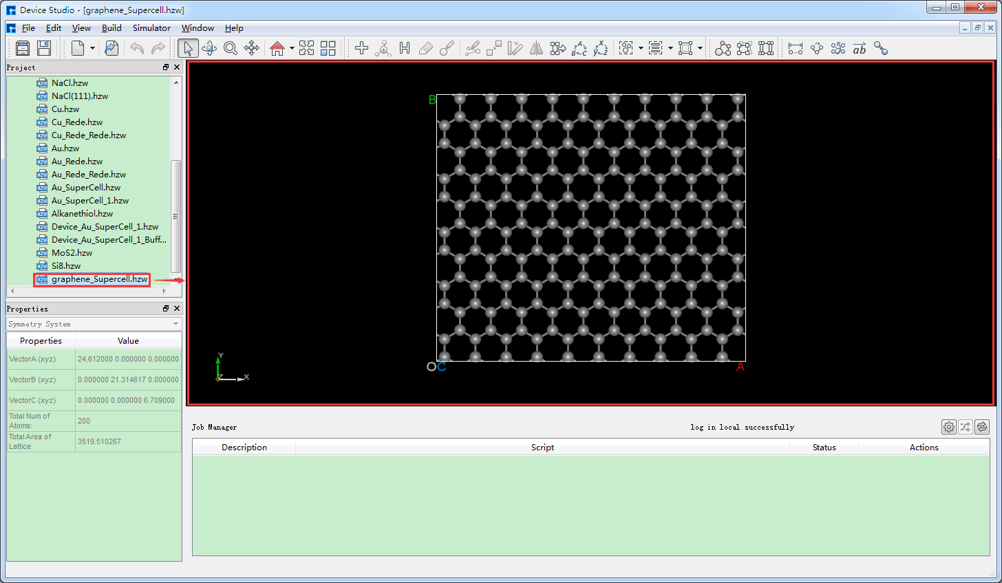
fig. 7.1 Import the graphene supercell structure into the Device Studio interface
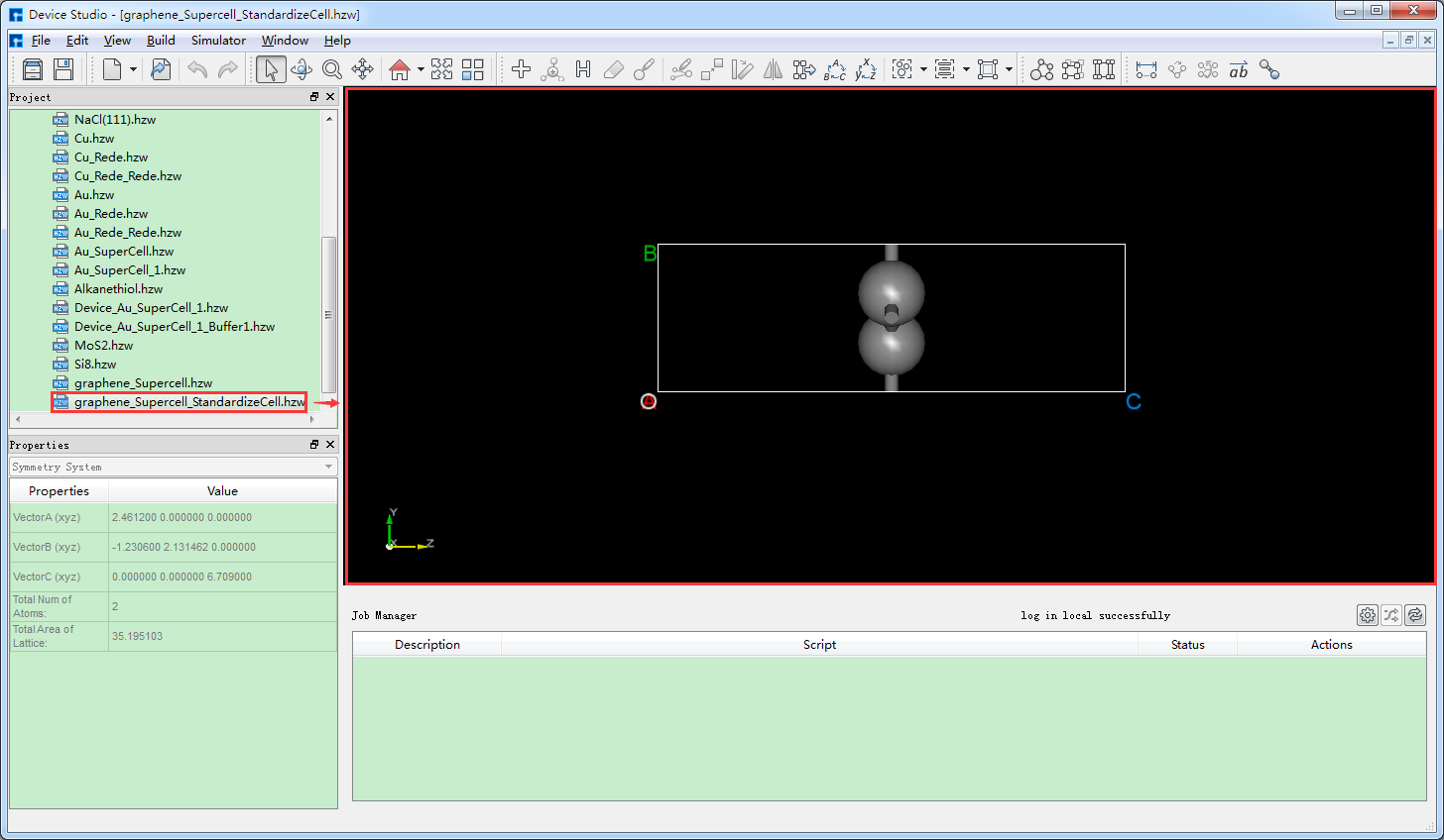
fig. 7.2 Graphene unit cell structure
Device Studio allows for the construction of flexible device structures. Taking the gold-alkanethiol-gold (Au-Alkanethiol-Au) flexible device structure as an example, first import the Au-Alkanethiol-Au molecular device structure into Device Studio as shown in fig. 7.3. In the fig. 7.3 interface, click Build → Bending of Device. The Bent interface for constructing the flexible device structure will pop up. In the Bent interface, select Both Side and set the relevant parameters as shown in fig. 7.4. Click Preview to preview the constructed flexible device structure, and click Build to complete the construction of the Au-Alkanethiol-Au flexible device structure. The structure file Au-Alkanethiol-Au_bent.hzw will be mounted in the Device Studio Project Explorer area. The Device Studio interface after constructing the Au-Alkanethiol-Au flexible device structure is shown in fig. 7.5.
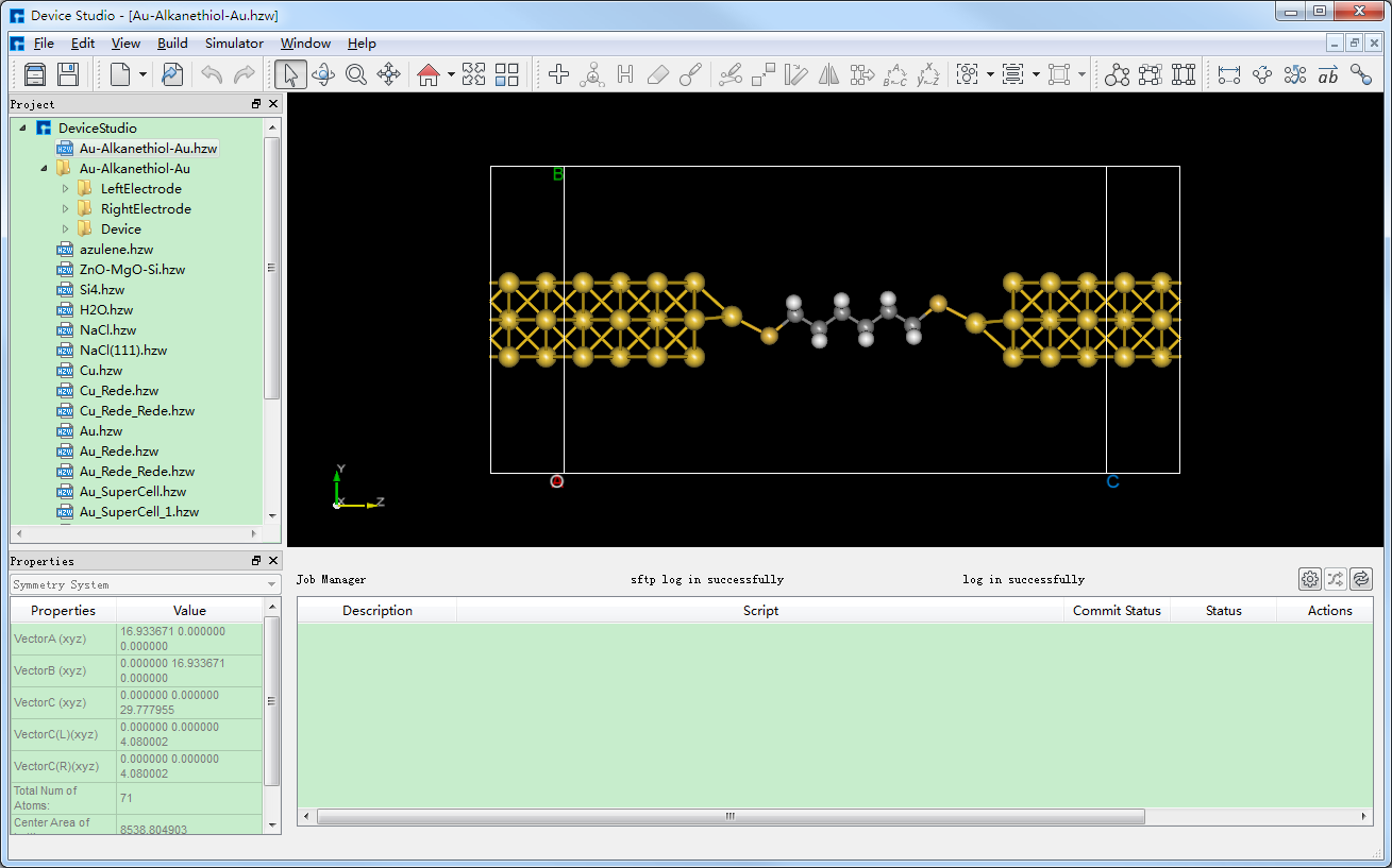
fig. 7.3 Device Studio interface after importing the Gold-Alkanethiol-Gold (Au-Alkanethiol-Au) molecular device structure
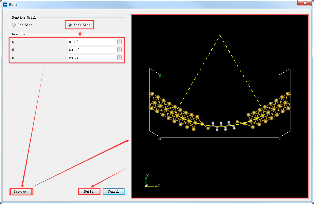
fig. 7.4 Constructing the Bent Interface of a Flexible Device Structure
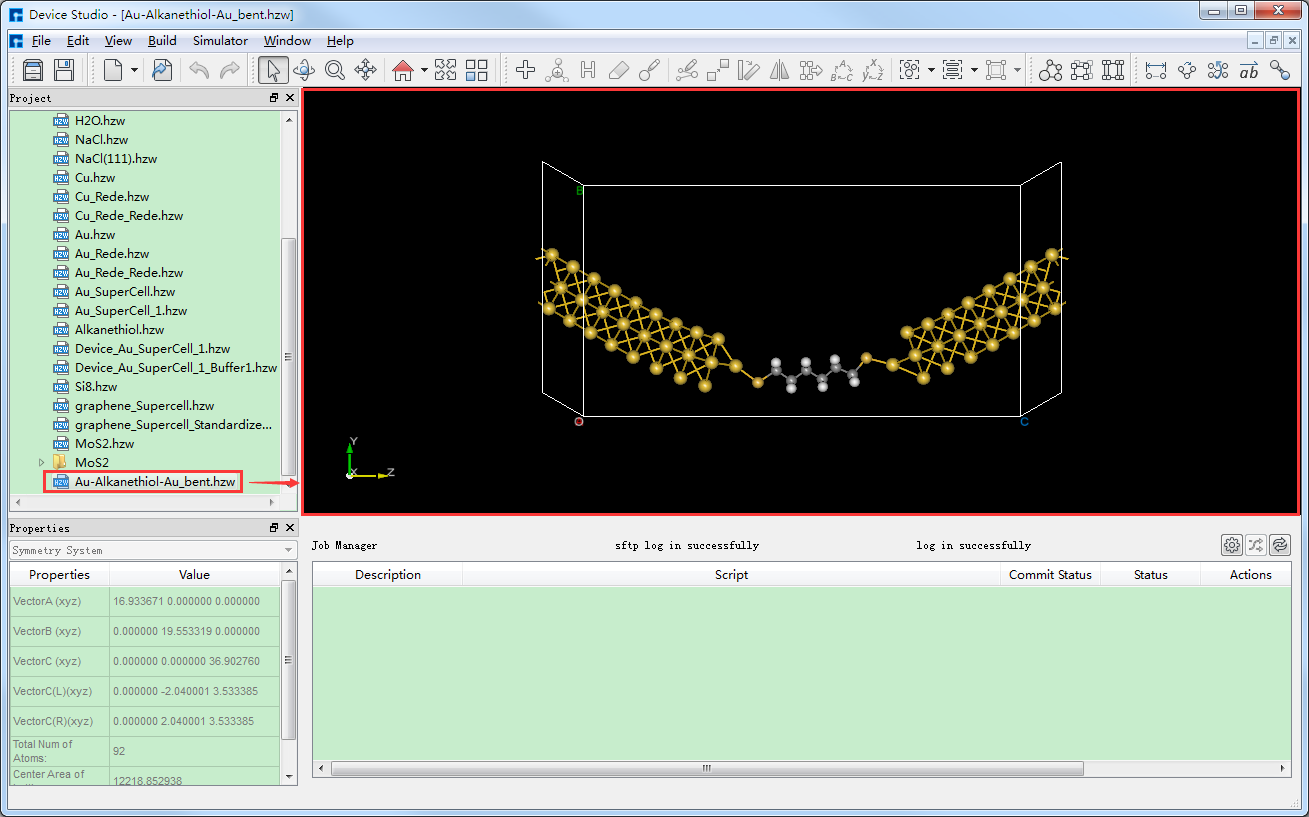
fig. 7.5 Device Studio interface for setting up a flexible device structure of Gold-Alkanethiol-Gold (Au-Alkanethiol-Au)
Device Studio can identify the space group and symmetry information of crystal structures. For example, in the Device Studio graphical user interface shown in fig. 7.6, for the GaSe crystal structure, clicking on Clicking Build → Symmetry will open the Symmetry interface as shown in fig. 7.7. The space group information for the GaSe crystal structure can be found in fig. 7.7 (a), and clicking Clicking the Operators button in the Symmetry interface displays the symmetry information of the GaSe crystal structure, as shown in fig. 7.8.
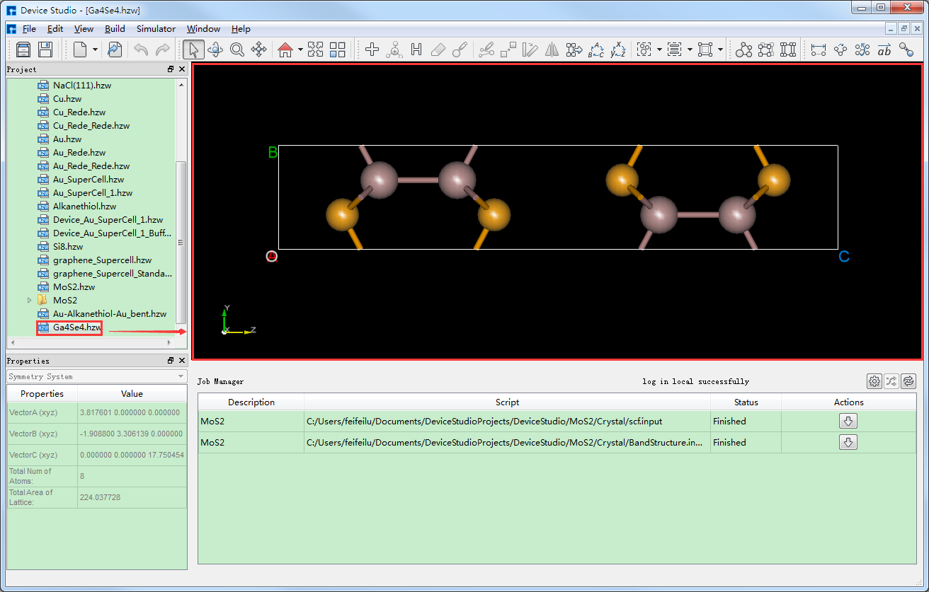
fig. 7.6 Device Studio interface displaying the GaSe crystal structure
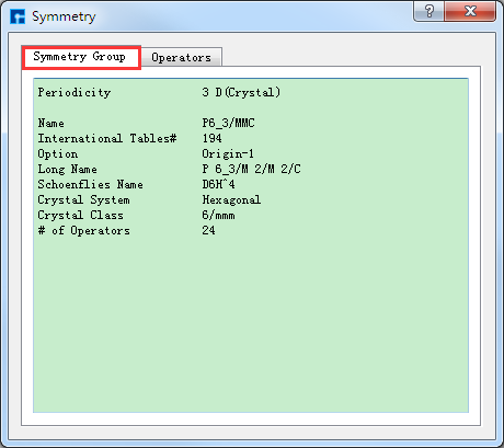
fig. 7.7 Space group information of the GaSe crystal structure |
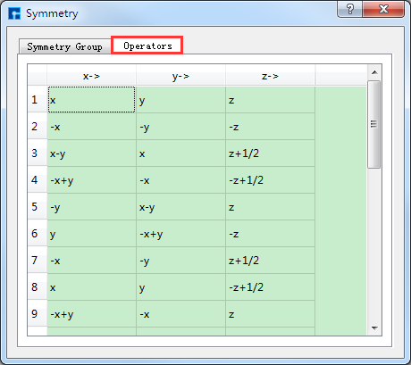
fig. 7.8 Symmetry information of the GaSe crystal structure |
Device Studio features a molecular structure decomposition function, which splits a crystal structure into individual molecular structures. For example, in the Device Studio graphical interface shown in fig. 7.9, for the C5H17AlN2O8P2 crystal structure, Clicking Build → Decomposition in the interface will decompose the C5H17AlN2O8P2 crystal structure into 6 molecular structures, as shown in fig. 7.10, fig. 7.11, and fig. 7.12. as shown in fig. 7.13, fig. 7.14, and fig. 7.15.
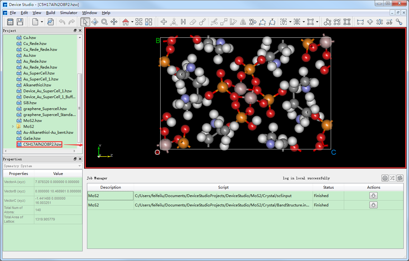
fig. 7.9 Device Studio interface displaying the crystal structure of C5H17AlN2O8P2
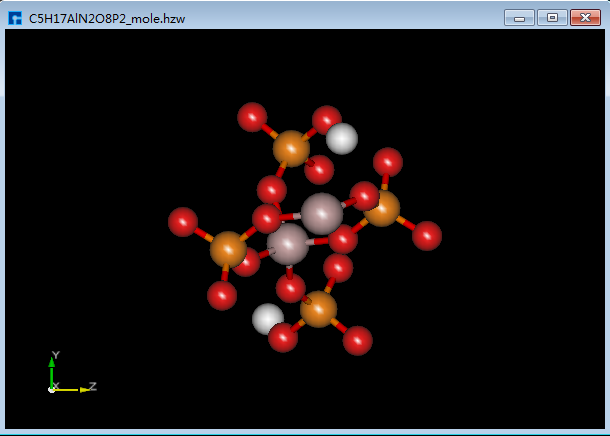
fig. 7.10 C5H17AlN2O8P2_mole |
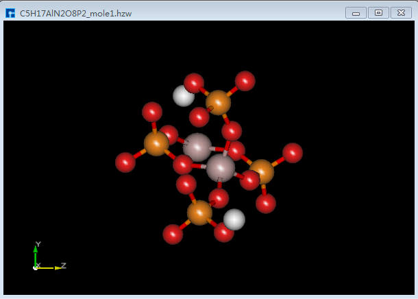
fig. 7.11 C5H17AlN2O8P2_mole1 |
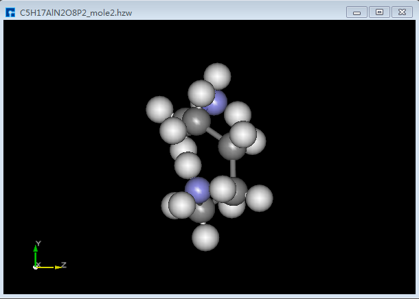
fig. 7.12 C5H17AlN2O8P2_mole2 |
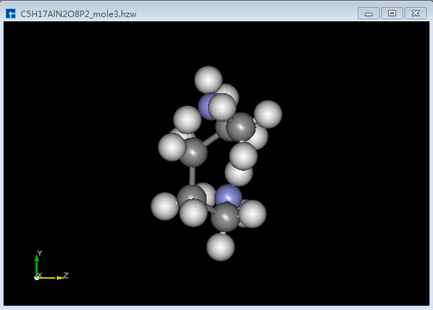
fig. 7.13 C5H17AlN2O8P2_mole3 |
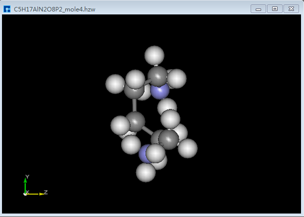
fig. 7.14 C5H17AlN2O8P2_mole4 |
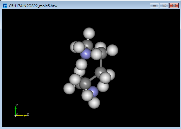
fig. 7.15 C5H17AlN2O8P2_mole5 |
Device Studio’s JobManager, as shown in fig. 7.16, integrates PuTTY and WinSCP modules, supporting the free configuration of server parameters, directories, and scripts. Commands are supported, along with automatic task status refresh and disconnection alerts. For information on configuring server connections in the Job Manager’s task monitoring and management area, please refer to the Server Connection section.
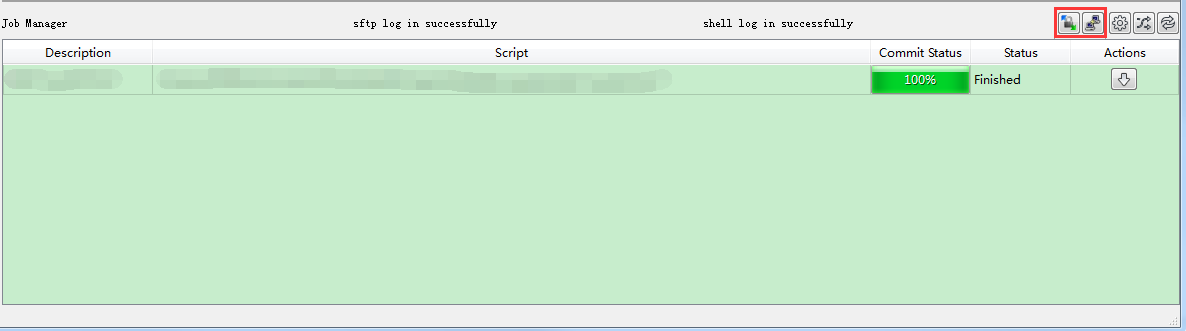
fig. 7.16 Device Studio’s JobManager
If the job calculation is complete, click the Download button under Action in the Job Manager to open the download interface for the calculation results, as shown in fig. 7.17, then click Download on the interface. The results can then be downloaded and viewed in the Project Explorer area of the software. Alternatively, users can connect to the server already connected to Device Studio by clicking the Open PuTTY and Open WinSCP icons in fig. 7.16, as shown in fig. 7.18 and fig. 7.19, respectively.
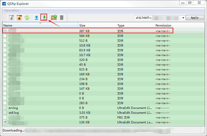
fig. 7.17 Device Studio’s JobManager interface for downloading computation results
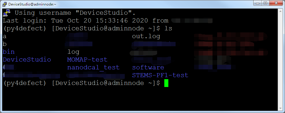
fig. 7.18 *PuTTY Server Connection Interface
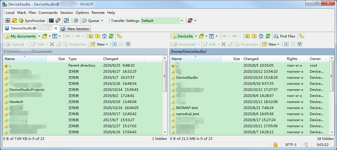
fig. 7.19 *WinSCP Server Connection Interface